
Thank you for purchasing the amazing Infinity One steam generator, suitable for residential and commercial use. Full manuals as PDFs will be emailed to you after purchase.
Introduction
Thank you for choosing our Infinity One steam generator product. Please read these instructions carefully and email this link to your installer/electrician/plumber before you begin, as it contains important information about installation and maintenance requirements.
“Infinity One” heavy-duty steam generators are available in specifications from 6 kW to 24 kW (larger than 12 kW are designed specifically for commercial only) and are supplied with two controls, one for residential installations and the other shot of steam control for commercial use, and a programmable thermostat controller
The commercial controller has a time and day feature, that allows you to program the generator to turn on and off automatically as needed. The generator can also be set to clean itself automatically. Once these settings have been saved, the Infinity One system can be left to work on its own. The Infinity One system must be checked on a regular basis for safety.
For commercial customers, it is also possible to have the generator generate steam by using a supplied push button control that you place outside of the steam room, the shot-of-steam button. When customers push the button it illuminates, and the boiler provides 30 minutes of steam. That avoids your cost of operating your steam room for most of the day without occupants. The Infinity One system can also be set to work using a countdown timer for a time you set, such as the next 90 minutes.
Our display tells you everything that the generator is doing… if it receives water, the elements are heating, when it reaches the selected temperature, draining, descaling, light on, fan on and timer setting. You can also lock the keys on the commercial control so users can’t adjust the settings – the steam room light, automatic drain valve, key-lock, altering the temperature display between Centigrade and Fahrenheit, as well as displaying the steam generator‘s status by the 8 LED’s on the panel, heating, water inlet, temperature, drain status and so on. Note also that one control we supply can control multiple “Infinity One” steam generators.
Every “Infinity One” steam generator is thoroughly tested before leaving the factory, so there may be some water inside the boiler on delivery.
Important Notes
Read the manual before installation and operation.
The Infinity One must be installed by a licensed electrician and plumber to avoid hazards.
The Infinity One must be electrically grounded. Be sure to disconnect the power supply before exposing the electrical connections.
Confirm the correct voltage to your steam generator, 1 or 3 phase. Single (1) phase is typically used for residential applications. Your system is supplied as ~220 volts, single phase (residential), but can be changed by the installer to 208 volts, 3 phase as needed.
For hard water areas, please use a water softener.
Water supply must have maximum of 20 lbs per square inch of pressure, 15 lbs. recommended and we recommend the use of a pressure reducing valve if necessary.
Safety Precautions
Elderly persons, pregnant women, or these suffering heart disease, high blood pressure, diabetes or not in good health are advised to seek medical opinion before using a steam room.
Do not smoke in the steam room.
Avoid using the steam room immediately after strenuous exercise.
Do not use the steam room when under the influence of alcohol.
Leave the steam room immediately if you feel sleepy, sick or uncomfortable.
Ensure there is good ventilation for the steam room.
We do not recommend that children under 16 use this product.
Commercial operators should post a notice of these precautions in a prominent position.
Steam entering the steam room will be scalding hot; take care to position the inlet nozzle(s) away from where users will sit and/or provide adequate guards/covers and post a notice to caution users.
Steam Generator Parts
Main circuit board
Transformer
Connections
Remove two plastic knockouts at the end of the generator and use rubber grommets to protect the cables. Use right hole for the power cable and left for the control cable. Plug the descaling pump plug into descaling socket next to the knockout holes.
Power connector and ground
| Part | Description |
| Transformer | 240v – 9v + 12v |
| Main Circuit Board | Control Center |
| Drain Valve | 3/4” Motorized Ball Valve |
| Inlet Valve | 240v Brass Solenoid Valve |
| Light Connection | 240v Light Output Switched by Keypad Max (100w) |
| Fan Connection | 240v Fan Output Switched by Keypad Max (100w) |
| Power In Connection | Terminal for connection of ~240/1 or 208/3 v power |
| Earth Connection | Earth Connection |
| Relay Circuit Board | Electrically operated switches for elements |
| Overheat switch | Boil dry protector operates at 212 F. Use Pin to reset |
| Louvers | Ventilation |
| Main Power Cable Entry | Cable entry and restraint for power cable |
| Control lead entry | Cable entry for control wire |
| Descaling Pump Connection | Socket for descaling pump |
| Information Chart | For info on Model, Voltage, Wattage and Amperage |
| Drain connection | 3/4” Female Brass |
| Water In Connection | 1/2” Male Brass |
| Acid Inlet | Hose Nipple for Silicone Descaling Tube Secure with cable tie |
| Water Probe Access | Water Probe Access Plate |
| Steam Outlets | 3/4” male steam outlets. Use brass fittings supplied |
Electrical and plumbing connections
| Model | Power | Current (amps) |
Size (mm) | Steam outlet |
Water Inlet |
Drain | Nozzle Type | |||
| kW | 1N~ | 3N~ | L | W | H | inches | inches | inches | ||
| Infinity One/6- | 6 | 26 | 8.6 | 535 | 260 | 380 | 3/4 (2of) | 1/2” | ||
| Infinity One/8 | 8 | 39 | 13 | 535 | 260 | 380 | 3/4 (2of) | 1/2” | 1/2” | Red |
| Infinity One/10.5 | 10.5 | 52 | 17.3 | 535 | 260 | 380 | 3/4 (2of) | 1/2” | 1/2” | Red |
| Infinity One/12 | 12 | 55 | 17.3 | 535 | 260 | 380 | 3/4 (2of) | 1/2” | 1/2” | Red |
| Infinity One/24-2 | 24 | 109 | 17.3 | 535 | 260 | 380 | 3/4 (2of) | 1/2” | 1/2” | Red |
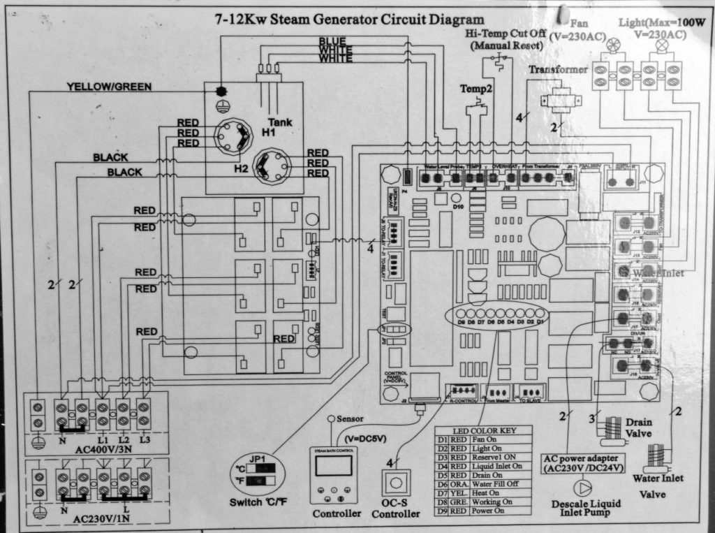
A qualified electrician will have no problem installing the system with the provided wiring schematic and with the help of the circuit diagram mounted behind the generator panel.
The steam generator electrical connections and control must be carried out by a qualified electrician. In case of a warranty claim, you must provide a copy of the invoice from the electrician and plumber.
Connections diagram and table
| Part | Description | Supplied |
| Water inlet | 1/2” copper pipe (maximum pressure 14.5 lbs. per square inch) | Not supplied |
| Pressure reducer valve | Set to 14.5 lbs. maximum. | Not supplied |
| Washing machine trap | Both drain and steam overflow feed into | Not supplied |
| Drain | 3/4” flexible hose | Not supplied |
| Steam Overflow | 1/2” copper pipe | Not supplied |
| Descaler inlet | Flexible silicone pipe secured with | Supplied |
| Descaling pump | Pumps descaling solution into generator | Supplied |
| Descaling solution container | Large plastic container filled with descaling solution | Not supplied |
| Pressure relief valve | Operates if the pressure in the boiler exceeds 17 lbs. per square inch | Supplied |
| Brass T junction | 3/4” to 3/4” and 1/2” brass fitting to fit steam pipe and pressure relief valve | Supplied |
| Brass T | 3/4” T fitting for secondary steam outlet | Supplied |
| 3/4” female cap | To block off secondary steam outlet | Not supplied |
| Steam pipe | Copper pipe from generator to steam inlet inside steam room (30 feet max length) | Not supplied |
| Steam inlet nozzle | 3/4” nozzle fitted inside steam room | Supplied |
| Control cable | 30′ 6 core cable to control keypad | Supplied |
| Control keypad | To be mounted inside or outside steam room | Supplied |
| Lighting circuit | 240V cable to lighting circuit (optional) | Not supplied |
| Mains input | Single or Three phase supply | Not supplied |
| Isolator Switch | Circuit breaker | Not supplied |
| Power to descaler pump | 240V power cable for descaler pump | Supplied |
Steam Pipe Connection Options
Wiring Multiple Generators
If more power is required than a single generator can provide, or you want a fault tolerant system where if one system fails, the others will continue to function until the problem resolved, one commercial controller may be used to control two or more steam generators. For example, if you need 24 kW steam generator output, you can use one controller to control two 12 kW steam generators or three 10.5 kW steam generators.
Ensure air flow into area where steam generator are located.
For commercial use, ensure good ventilation from at least two ducts within the housing of the generator
Isolate the power supply before installation.
Confirm that the model you have selected is suitable for your steam room. Please refer to chart below.
Mount the steam inlet nozzle approximately 8-12 inches from the floor. It should be at least 12 inches from the nearest person to avoid burns.
If the steam generator is installed in an inaccessible location, ensure that both the electrical power and water supply can be isolated in an emergency. That usually means a electrical cut-off switch and water valve near to the generator or easily accessed.
To use the steam generator in single phase the L1, L2 and L3 must be linked together with the copper bridges that are supplied. See diagram.
The minimum water inlet pressure is 4 lbs. per square inch and the maximum is 14 lbs. per square inch. For higher pressures use a reducer before the valve as shown in diagrams.
The steam pipe from steam generator to your steam room should be kept to a minimum length. Pipes longer than 10 feet should be insulated to prevent heat loss. Steam pipes will be hot during use and must be protected against accidental contact with wood or other flammable material.
Steam entering the steam room will be scalding hot; take care to position the inlet nozzle away from where users will sit and/or provide adequate guarding, and post a notice to caution users in commercial installations.
Keep the number of right angle bends to a minimum and ensure that the run does not create a “trap” into which condensate would cause a blockage. For example, the pipe must not go down and then up.
There must be no valve or other blockage in the steam pipe
The steam pipe should be metal, preferably copper or other material that can endure 300°F temperature.
We do not recommend installing the steam generator outdoors or where it might be affected by frost or get wet. Allow for a minimum space of 20 cubic feet to install the generator.
The steam generator should be level side-to-side and front to back, and should be installed so that the arrows on the case point up.
Do not install the steam generator in close proximity to hazardous substances.
Generator Size
| Model | kW rating | Maximum room size in cubic feet, cf. Multiply size by 0.8 for ceramic tile and 0.5 for natural stone, marble or slate, etc. | Ceramic finish | Marble finish |
| Infinity One/6 | 6 | 150 cf, example, 4’x5’x7.5′ | 120 cf, example, 4’x4’x7.5′ | 75 cf, example, 3.25’x3.25’x7.5′ |
| Infinity One/8 | 8 | 250 cf, example, 6’x5.5’x7.5′ | 200 cf, example, 5’x5’x7.5′ | 125 cf, example, 4’x4’x7.5′ |
| Infinity One/10.5 | 10.5 | 425 cf, example, 7’x8’x7.5′ | 340 cf, example, 6.75’x6.75’x7.5′ | 212 cf, example, 5.25’x5.25’x7.5′ |
| Infinity One/12 | 12 | 575 cf, example, 8’x9.5’x7.5′ | 460 cf, example, 8’x8’x7.5′ | 288 cf, example, 6.25’x6.25’x7.5′ |
| Infinity One/24-2 | 24 | 1,000 cf, example, 11’x12’x7.5′ | 800 cf, example, 10.25’x10.25’x7.5′ | 500 cf, example, 8.25’x8.25’x7.5′ |
This table should be used for guidance only. Please note that the size of generator required to heat a particular size of steam room will vary according to a number of factors including the type of material used for construction, the height of the steam room and the ambient temperature.
For lightweight materials such as plastics and laminates 1 kW will heat up to 30 cubic feet of air. For dense materials such as natural stone, and to a lesser extent ceramic tile they will conduct the heat away more rapidly. Allow for up to 2kW per 30 cubic feet of air. Hot air rises, so restricting the height to around 7-7.5 feet will ensure the user is sitting in the steam. For higher ceilings you may need to increase the power requirement.
The following table is given as a guide; ambient air temperatures and frequency of use (number of door openings) can also affect the power requirements.
Steam Generator Location
The steam generator should be installed in a dry, well ventilated location in close proximity to the steam room. It can be installed on the floor or hung on a wall.
To hang the generator on a wall drill 3 holes, 8 mm in diameter in accordance with the table below. Fix the top 2 screws in place first then hang the generator by the 2 keyhole shaped holes in the back plate. Then with the front cover removed fix the 3rd screw to secure the unit in place.
The steam generator can be installed anywhere that is dry and has an airflow.
Possible locations:
Plant Room
Closet in an adjacent room
In an attic or loft.
Up to 5 feet beneath the unit in a basement
Important notes-
The steam pipe should be insulated and not be farther than 35 feet from the steam room.
Do not reduce size (width) of the steam pipe at any point. The steam pipe must not go down and then up, as this will create a water condensation trap and damage the steam generator.
Water and Steam Connections
The water supply pipe and steam pipe should comply with local government standards, if any, as should the generator.
Connect the water inlet valve of the generator to the water supply using a flexible hose with 1/2 inch fittings. Install a water cut-off valve near the generator.
Use the same dimension copper pipe to connect the steam outlet (1/2 inch or 3/4 inch) to connect it and if the steam pipe is longer than 15 feet it should be insulated. During use, the steam pipe will be very hot and must be protected against accidental contact with flammable or other objects.
Note that according to the location it may be necessary to attach an additional length of pipe to the pressure relief valve in order to divert the steam flow to a safe direction should the valve operate.
Connect the drain outlet to a suitable drain, via a copper pipe with the appropriate fittings.
Installation for controller and temperature probe-
The control is water resistant and can be installed inside or outside the steam room according to your needs.
For a better connection and to eliminate any future connection problems, spray connection fluid or aerosol oil spray on the pins of the PS/2 cable (5pin cable) before plugging into the circuit board as suggested by the product’s label.
Ideally the control panel should be installed at a height of about four feet for ease of use.
Installation
Open the front cover of steam generator. Pin the control cable (6 cores) and temperature sensor cable (2 cores) to the relevant ports.
Control panel installation- pin one end to circuit board ports in steam generator and connect the other end to the controller’s cable.
Temperature probe installation- the temperature probe is installed inside the steam room at approximately one foot from the ceiling, and away from the steam outlet. Use a 4 mm screw to secure it in place and then connect to the wire from the controller.
Attach the protective cover (supplied) over the temperature sensor.
Installation of power supply and control cable
Confirm the correct voltage of power supply and wires.
Remove the knock-out for the power cable entry and use a rubber grommet to protect the cable; connect to the conductors to the correct terminals – for single (one) phase power supply use the copper bridge connectors, for three phase supply remove them. (Extra bridges are provided, see diagram.)
Remove the knock out for the control cable entry and use a rubber grommet to protect the cable. Connect the cable to the relevant port on circuit the main circuit board.
Keep the power supply wire and control cable separate to prevent electrical field interference to the control cable signal.
Installing a light
There is a 240v power supply inside the steam generator labeled “Light”. This is rated to a maximum of 100 watts. The button on the keypad will turn this power supply off and on. This power supply is protected by a fuse on the main circuit board, but you can add your own fused spur for extra protection if you prefer.
Installing a Fan
Same as above for a light. Generally, we do not recommend installing a fan in a steam room, but suggest that after use and the room has cooled, to leave the door open to allow rapid drying and avoid mold development.
Connecting to the Descaler
The Infinity One generator is able to run an automatic descale cycle by pumping descaling solution directly into the tank. This can be set to occur at regular intervals using the controller as described elsewhere.
The pump supplied should be connected via the supplied silicon hose to the generator, and the container of descaling solution that you should be able to buy locally or on the internet.
The diagrams show how the descaling solution should be connected via the pump. Ensure the ends of the hose are held in place with cable ties.
Steam on Demand (Shot-of-Steam) Function
Commercial users may wish to take advantage of the steam-on-demand function which will allow customers to press the steam-on-demand button located inside or outside of the steam room. The generator will create steam for 30 minutes, then return to an idle state until activated again. This function reduces running costs and maintenance frequency.
Commercial Programmable Controller User Instructions
Display and Buttons
Turning On/Off. To turn on, push the ON button. You should now see the default display.
When power has been switched on to the Infinity One system the keypad will sound a short beep to indicate that it has been powered on.
Time and Day – Press push repeatedly until you reach the Time and Day settings. Push for OK.
You can now use the increase and decrease the time or day, left and right buttons to set the hours, minutes and day.
Setting Temperature – you can set the temperature between 95 and 140 degrees Fahrenheit.
If you are a new user we recommend beginning at around 100 degrees Fahrenheit and when you are comfortable with this temperature start to increase slowly by 2 degrees Fahrenheit between each bathing session.
Push to enter setting
Working Modes
Mode A – This is a countdown timer. You can set for up to 4 hours or for continuous heating.
Change the time using the up and down keys. Press to save the setting
Once set the home screen should look like this.
Mode B – Steam On Demand. (Commercial use only) Install a button outside of the steam room. When a customer pushes the button they get 30 minutes of steam. With the steam-on-demand feature you only need to set the temperature of the room. When the red button is pushed, it will illuminate to let users know the generator is working.
Mode Auto – Program specific times for the generator to turn on and off throughout the day. Once setup, the Infinity One system will remember to turn on or off at these same times every day.
You can choose in the morning from between 0.00 – 11:59 (noon). The afternoon setting are between 12:00 – 23:59 (midnight).
To activate morning (1) or afternoon (2) change the X to a check mark and set the time you want the Infinity One system to turn on and off.
If you turn off power to the Infinity One system, it will forget your settings and reset to the default.
Auto Descale
These instructions are typically for commercial users only. Gyms and health clubs typically run generators for up to 18 hours a day. Residential applications are perhaps only 2% of that usage. You may only wish to descale a few times a year to maintain peak performance and reliable function.
Set the Infinity One system to automatically descale itself once per week. Once set, the Infinity One system will descale (clean) itself at the same time every week.
The descaling solution, typically made from powder, will still need to be topped up. A 120 liter drum (~30 gallons) will be enough for about 10 descales before refilling with acid. Mix 11 pounds of acid for the entire 120 liters (~30 gallon) of acid or around 1.5 ounces of acid per liter. Eleven pounds of citric acid is about $30.
For some users it may not be necessary for you to descale the generator every week as you may not be in a hard water area, or you may only be operating the Infinity One system for a few hours, or less, per day.
In this case we advise not to have the Infinity One system set up for a regular descaling cycle and only switch on the descaling cycle when you need it. You must remember though that once the cycle has been completed you must turn the check mark to X to turn the weekly descale off.
To setup descaling push Push to enter. The default is Sunday between midnight 00:00 and 8:00 in the morning. To activate descale change the X to a check mark.
You can also adjust the day and time that the descale will operate. We advise a minimum of 4 hours to complete the deep cleaning.
Note the screen must be turned off for the descale cycle to run.
Drain
You will never need to drain the Infinity One system as it automatically drains itself. On occasion, if you are using the Infinity One when there are lightning storms, the unit may not switch on after as the automatic drain cycle is not properly completed. Just press the drain button, wait a few minutes and the system should be ready for a regular cycle.
After switching your steam generator off it will drain the water out so that there is never a concentrated solution of limescale in the tank. It will also completely drain and flush itself after it has been turned off at the control, but not if you cut power to the entire system.
To drain the Infinity One system, you first need the control screen to be off, so if it is already on push the On/Off button to turn it off. Now push the Drain button. The screen will illuminate and indicate the drain symbol.
Light and Fan
The light and fan will stay on if the keypad is off, so that if you use the room as a shower the light can still remains on.
To turn the fan or light on or off just push the button with the light or fan symbol.
Both the light and the fan are supported up to 100 watts.
Screen Lock
To lock the screen push the ‘+” button for 5 seconds.
When the controller is locked the ‘light’ button and ‘on/off ‘ button will still be functional.
Troubleshooting guide
Please note that we recommend all repairs are carried out be a suitably qualified person.
| Trouble description | Cause
Something is wrong with: |
Solution |
| No steam | Settings are not correct
Connection Power supply Transformer Main circuit board controller Control cable or port Connection Fuse |
Has the control been set up correctly?
Is water light on – check water supply – check valve coil for continuity? Remove and clean water level probe with emery cloth. Descale Infinity One system. Check fuse. Check power output from transformer. Replace Main PCB. |
| Water coming out of steam nozzle | Water Level Probe | Remove and clean water level probe
Check connections to and from water level probe. |
| Circuit breaker tripping | Element failure. Loose Earth Wire
Faulty connection |
1. To check elements use a insulation tester, or fault find by disconnecting individual elements one by one.
2. Check earth connections are tight. 3. If above fails, return generator to supplier for repair, warranty information below. |
| Temperature window displays “LC” | The temp sensor connection | 1. Check connection or change temp sensor.2. If above fails replace sensor. |
| Temperature window display “HC” | Temp sensor has short circuit | 1. Check connection or change temp sensor.2. If above fails replace sensor. |
| Water runs through steam nozzle in room. | Water inlet valve
Level sensor |
1. Turn Infinity One system off, if water continues, clean inlet valve or replace.2. If runs while Infinity One system is on, try 1 above. If fails, clean water probe and check connection to circuit board. |
| Generator works when switched off on the control panel. | Relays | Replace relay PCB. |
| Filling symbol is flashing | Check water supply. |